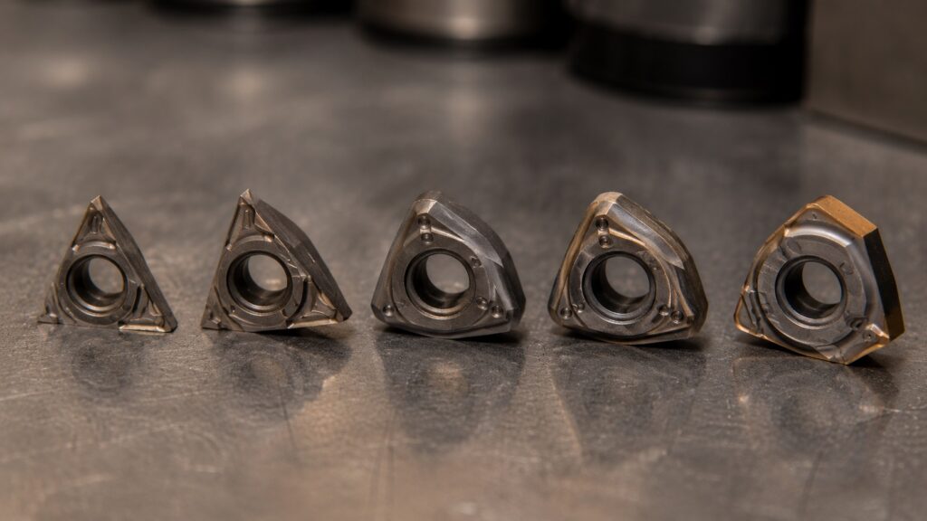
What Causes Chatter Marks on Turned Parts?
Chatter marks on turned parts are usually caused by vibration between the cutting tool, workpiece, and CNC lathe setup. To fix CNC chatter marks on turned parts, start by reducing tool overhang, improving workpiece support, adjusting spindle speed, checking insert geometry, and making sure the finishing pass is actually cutting instead of rubbing.
Quick Diagnostic Cheat Sheet
Before changing speeds, feeds, or inserts, use this quick reference table to identify the most likely source of chatter.
| Symptom | Most Likely Cause |
|---|---|
| Chatter only at the end of a shaft | Insufficient workpiece support |
| Chatter only during boring | Excessive boring bar overhang |
| Chatter appears after insert change | Incorrect insert geometry |
| Chatter starts on finish pass | Feed rate too low or finish allowance too small |
| Chatter changes when RPM changes | Harmonic resonance |
| Chatter remains regardless of parameters | Rigidity or machine condition issue |
| Chatter appears farther from the chuck | Workpiece deflection |
| Random marks inside a bore | Chip recutting problem |
Chatter is one of those machining problems that looks simple from the outside but can waste hours on the shop floor.
The part may be running within size. The insert may still look usable. The program may have worked fine on a shorter batch last week. Then suddenly the surface finish shows repeating waves, the machine starts singing, and every part coming off the lathe looks slightly wrong.
On turned parts, chatter is not just a cosmetic problem. It can affect diameter consistency, bearing fits, sealing surfaces, threaded sections, and customer acceptance. A shaft with visible chatter might measure close enough with calipers but still fail where surface finish or roundness actually matters.
The good news is that CNC turning chatter is usually fixable if you troubleshoot it in the right order. The mistake many operators make is changing feed and speed first, before checking the basic mechanical setup.
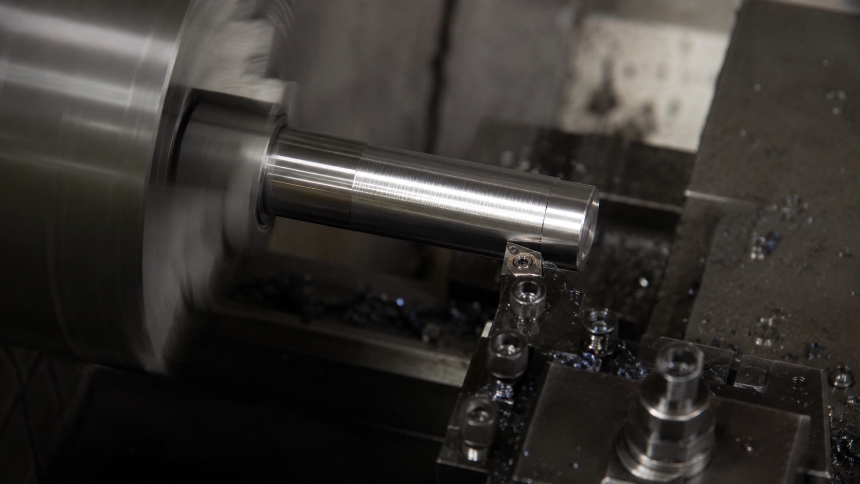
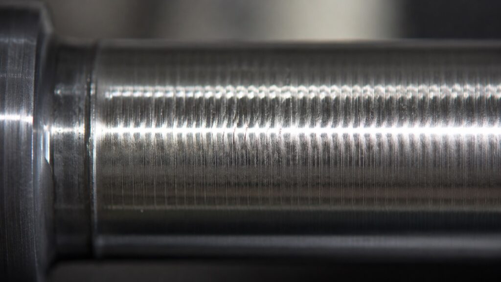
What Chatter Marks Look Like on Turned Parts
Chatter marks on turned parts usually appear as repeated waves, rings, spirals, or uneven bands on the machined surface. On OD turning, they often show as a regular pattern around the diameter. On boring operations, they may look more severe because the boring bar is less rigid than an external turning tool.
You may also hear it before you see it. A high-pitched squeal often points toward tool vibration or poor cutting conditions. A heavier rumble can suggest workpiece movement, unsupported length, or machine rigidity problems.
A small amount of tool noise is normal in turning. True chatter has a repeating pattern. It usually gets worse when the tool reaches a less supported area of the part, enters a long finishing pass, or cuts near a shoulder where cutting pressure changes quickly.
Why CNC Chatter Happens During Turning
CNC chatter happens when cutting forces excite vibration in the machine, tool, holder, or workpiece. In turning, the most common source is the interaction between the insert and the rotating part.
If you’re newer to machining, understanding the fundamentals of machine rigidity, cutting forces, and tool deflection can make chatter problems much easier to diagnose. Our CNC Basics guide explains the core principles behind machine behavior during cutting operations.
The cutting edge does not simply remove metal in a perfectly smooth motion. It pushes, shears, deflects, and unloads. If the tool or workpiece starts vibrating, the insert cuts over the tiny waves left by the previous rotation. That creates uneven chip thickness, which creates more vibration.
That is regenerative chatter.
Regenerative chatter is not limited to turning operations. Similar vibration mechanisms can occur during milling when chip thickness varies from one cutter engagement to the next. Our guide to trochoidal and peel milling explains how modern toolpaths help reduce unstable cutting forces.
In practical shop terms, the cut starts feeding its own vibration. Once that pattern develops, simply “taking it easy” does not always fix it. Sometimes reducing the feed makes the insert rub more, which makes the finish worse.
That is counterintuitive, but common.
A turning insert needs enough feed pressure to cut cleanly. If the feed is too light for the nose radius and edge preparation, the insert can skate over the surface instead of shearing the material. The result is often a shiny but wavy finish, especially on tougher steels and stainless.
First Check: Is the Part Unsupported?
Before touching the program, look at the part setup.
Long turned parts are one of the easiest ways to create chatter. If too much material sticks out from the chuck without tailstock or steady rest support, the workpiece behaves like a spring. It may look solid when stationary, but under cutting pressure it can flex, vibrate, and ring.
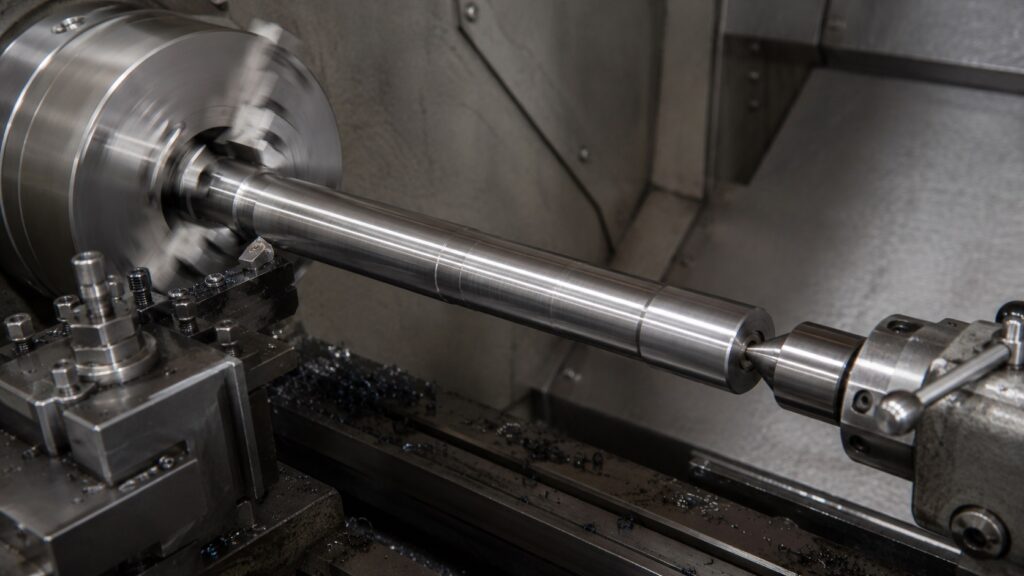
A common warning sign is chatter that gets worse farther away from the chuck. The surface near the jaws may look acceptable, while the far end shows waves or a rough spiral pattern.
To fix this:
Use tailstock support when the part length allows it.
Use a live center with proper pressure, not excessive force.
Use a steady rest for long or slender shafts.
Reduce the amount of stock sticking out from the chuck.
Rough closer to size before extending the part farther out.
Avoid heavy finishing cuts on unsupported sections.
Too much tailstock pressure can also cause trouble. It may bend slender parts slightly, create taper, or overload the center. The goal is support, not brute force.
In production turning, this is where experience matters. A part can feel rigid by hand and still chatter under the tool because cutting pressure is not gentle. The machine is testing the setup harder than your hand ever will.
Check Tool Overhang and Holder Rigidity
Tool overhang is one of the biggest causes of chatter in CNC turning.
The farther the tool extends from the turret, boring holder, or tool block, the easier it vibrates. This matters even more with boring bars because boring bars are naturally less rigid than OD turning tools.
For OD turning, keep the toolholder as short and solid as practical. Make sure the holder is properly seated, the turret face is clean, and the insert pocket is not damaged.
For boring, use the largest boring bar that fits the bore. A small boring bar may clear the hole, but clearance alone does not mean stability. If the bar is too small or too long, chatter is almost guaranteed on deeper bores.
As a rough shop rule, steel boring bars start becoming sensitive as length-to-diameter ratio increases. Carbide boring bars and damped boring bars can handle more overhang, but they still have limits.
To reduce tool-related chatter:
Shorten the stick-out.
Use a larger shank tool or boring bar.
Check that the tool block is tight.
Use a carbide or damped boring bar for deeper bores.
Replace worn screws, clamps, or insert seats.
Avoid using damaged holders for finishing.
One overlooked issue is insert seating. If a chip is trapped under the insert, the cutting edge may sit slightly wrong. That tiny error can create vibration, poor finish, and inconsistent size.
Adjust Spindle Speed Before You Blame the Insert
When chatter starts, many operators reduce RPM and feed together. Sometimes that works, but it can also move the cut into another unstable zone.
A better first move is to change spindle speed by a small percentage.
Try adjusting RPM up or down by 10–15 percent while keeping the chip load reasonable. Chatter often disappears suddenly when the cut moves away from a resonant frequency.
If the chatter improves when RPM changes, the issue is probably related to vibration harmonics rather than simply a dull insert. If nothing changes, look harder at rigidity, support, and tool geometry.
Sometimes what appears to be a tooling problem is actually caused by programming decisions. Excessive tool engagement, poor toolpaths, or aggressive parameter choices can all contribute to instability. Our article on common CNC programming errors covers several examples.
On CNC lathes with constant surface speed, also check whether chatter appears as the diameter changes. CSS can change RPM continuously during the cut. That is useful for maintaining surface speed, but on some setups it may pass through a vibration-prone zone.
For difficult chatter, it can be worth testing fixed RPM during troubleshooting. Once you find a stable range, you can decide whether CSS still makes sense for that operation.
Do Not Make the Feed Too Light
A very light finishing feed sounds safe, but it can cause chatter.
Turning inserts are designed to work within a feed range. If the feed per revolution is too low compared with the insert nose radius, edge hone, and material, the insert may rub instead of cut. Rubbing increases heat, work hardening, and vibration.
This is especially noticeable in stainless steel, alloy steel, and tougher materials that dislike hesitation.
If your finish pass is noisy and the chip looks thin, dusty, or inconsistent, the feed may be too low. Increasing feed slightly can sometimes make the cut quieter because the insert finally starts shearing properly.
That does not mean you should run aggressively on every finish pass. It means the feed must match the insert geometry and material.
For finishing, check:
Is the feed too light for the nose radius?
Is the insert edge too strong or too honed for a light cut?
Is the depth of cut below the insert’s effective cutting range?
Is the material work hardening because the tool is rubbing?
Are chips coming off consistently?
A stable finish pass usually produces a consistent chip and a steady sound. If the insert is just polishing the surface, chatter can appear even though the cut looks “gentle” on paper.
Insert Geometry: Nose Radius, Rake, and Edge Prep
Insert choice has a major effect on chatter marks.
A larger nose radius can improve surface finish because it creates a smoother theoretical finish at the same feed. But a larger nose radius also increases radial cutting pressure. On a weak setup, that extra pressure can trigger chatter.
This is one of the most common counterintuitive turning problems: the insert chosen for a better finish can make the real finish worse.
If the part is slender or the setup lacks rigidity, a smaller nose radius may run more quietly. For example, switching from a large finishing radius to a smaller radius can reduce cutting pressure and improve stability, even if the theoretical surface finish number looks worse.
Positive rake inserts usually cut with lower pressure than negative rake inserts. That can help on light machines, small parts, thin-walled parts, and long unsupported workpieces. Negative inserts are stronger, but they often need more rigidity and horsepower.
Machine rigidity plays a major role here. Smaller hobby machines and benchtop lathes are generally more sensitive to vibration than heavier industrial equipment. If you’re machining on a smaller machine, our guide on whether a minilathe is worth it discusses some of the practical limitations that affect surface finish and chatter control.
Edge prep matters too. A heavily honed insert edge is strong, but it may not cut cleanly at light feeds. A sharper ground insert can reduce cutting pressure, but it may chip faster in interrupted cuts or scale.
For chatter-prone turned parts, consider:
Smaller nose radius if radial pressure is too high.
Positive rake geometry for lower cutting forces.
Sharper inserts for light finishing cuts.
Stronger inserts for roughing or interrupted cuts.
Wiper inserts only when the setup is rigid enough.
Wiper inserts can produce excellent finishes, but they are not magic. On a flexible setup, they may increase contact and worsen vibration.
Depth of Cut and Finish Allowance
A poor finishing allowance can create chatter even after a good roughing pass.
If the finish pass removes too little material, the insert may rub. If it removes too much, cutting pressure may rise and excite vibration. The correct finish allowance depends on material, insert geometry, part rigidity, and required finish.
A common mistake is leaving a finish pass so light that it cannot clean up the roughing marks properly. The insert follows the previous surface instead of correcting it. If the roughing pass already left vibration marks, the finishing pass may repeat them.
For better results:
Leave enough stock for the finish tool to cut cleanly.
Do not leave a springy, inconsistent semi-finish surface.
Use a stable semi-finish pass before final finishing when needed.
Avoid extremely light “spark-out” style passes unless the setup supports it.
Keep the final pass consistent across the full length of the part.
On long shafts, it may be better to use a conservative roughing pass, a semi-finish pass to stabilize the surface, and then a controlled finish pass. Trying to fix everything with one beautiful final pass often fails when the part is flexible.
Workholding: Chuck Pressure and Jaw Contact
Workholding chatter is not always caused by loose clamping. Sometimes the problem is uneven or excessive clamping.
If jaws grip poorly, the part can move. If jaws grip too hard, thin-walled parts can distort. If soft jaws are bored incorrectly, the part may not sit evenly, and cutting pressure will excite vibration.
For turned parts, jaw contact matters as much as clamping force.
Check:
Are the jaws contacting evenly?
Are soft jaws bored at the correct clamping pressure?
Is the part seated firmly against a stop?
Is the gripping length enough for the cutting load?
Are the jaws bell-mouthed, worn, or packed with chips?
Is the part thin enough to distort under chuck pressure?
For thin-wall parts, reduce cutting pressure before simply increasing chuck pressure. More clamp force may hide movement but create roundness problems after unclamping.
In production, this can become frustrating because the part looks good in the chuck and measures differently after release. That is a workholding and stress problem, not just a surface finish problem.
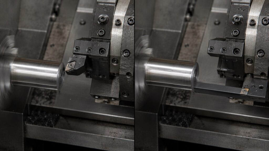
OD Turning vs Boring Chatter
How Chatter Develops in External Turning vs Boring Operations
The illustration below shows why boring operations typically chatter more easily than external turning.
In OD turning, the cutting tool is supported close to the turret, creating a relatively rigid structure. Any vibration generated at the insert has limited leverage to amplify.
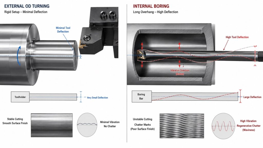
In boring operations, the boring bar acts like a cantilever beam. As bar overhang increases, even small cutting forces can create significant deflection. That deflection leaves microscopic waves on the bore surface. During the next spindle revolution, the insert cuts through those waves again, increasing chip thickness variation and feeding additional vibration into the system.
A useful way to visualize chatter is to imagine the insert continuously cutting over its own mistakes. Every vibration leaves a tiny surface wave. If the next revolution hits that wave at the wrong phase angle, the vibration grows instead of disappearing.
Figure Recommendation
- Left side: Stable OD turning setup with short tool overhang
- Right side: Long boring bar showing amplified deflection
- Include arrows indicating vibration direction
- Show exaggerated surface waves representing regenerative chatter
- Label:
- Tool Deflection
- Surface Wave Pattern
- Regenerative Chatter Loop
- Increased Overhang = Reduced Rigidity
OD turning chatter and boring chatter often need different solutions.
OD turning usually gives you more rigidity because the tool is supported closer to the turret and the workpiece is visible. You can often solve OD chatter by improving support, reducing tool overhang, adjusting RPM, or changing insert geometry.
Boring is less forgiving. A boring bar is cantilevered inside the part, and the cutting edge is harder to observe. Chips may pack inside the bore, coolant may not reach the cutting zone properly, and the bar may vibrate before the operator notices visible marks.
For boring chatter:
Use the largest bar possible.
Keep bar overhang as short as possible.
Use through-coolant when chip evacuation is poor.
Reduce nose radius if cutting pressure is too high.
Try a sharper positive insert.
Use a damped boring bar for deeper bores.
Avoid re-cutting chips inside blind holes.
Boring chatter often shows as a rough, torn, or wavy bore finish. If chips are trapped inside the bore, the problem may look like chatter but partly come from chip re-cutting.
Step-by-Step Troubleshooting Process
Use this order when fixing CNC chatter marks on turned parts.
| Step | What to Check | What It Usually Means | Practical Fix | Expected Outcome |
|---|---|---|---|---|
| 1 | Where chatter appears | Location helps identify the weak component in the system | Determine whether the issue is workholding, tooling, or cutting parameters | Root cause becomes easier to isolate before random parameter changes |
| 2 | Workpiece support | Long unsupported parts often vibrate under cutting load | Add tailstock support, steady rest, or reduce stick-out | Chatter intensity should decrease toward the unsupported end of the part |
| 3 | Tool overhang | Excessive overhang reduces rigidity dramatically | Shorten tool projection or increase boring bar diameter | Vibration frequency becomes lower or disappears completely |
| 4 | Insert condition | Worn or chipped inserts create unstable cutting forces | Replace insert and inspect insert seat for chips or damage | Cutting sound becomes smoother and surface finish improves immediately |
| 5 | RPM sensitivity | Resonance is likely involved | Increase or decrease spindle speed by 10–15% | High-pitched chatter often disappears almost instantly when leaving the unstable zone |
| 6 | Feed and depth of cut | Tool may be rubbing instead of cutting efficiently | Increase feed slightly or adjust finishing allowance | Chips become more consistent and surface waviness is reduced |
| 7 | Workholding setup | Part movement or distortion may be occurring | Improve jaw contact, rebore soft jaws, or adjust chuck pressure | Surface finish becomes more uniform across the full part length |
| 8 | Chip control | Recutting chips can mimic or trigger chatter | Improve coolant delivery, chipbreaker selection, or evacuation | Random marks disappear and cutting sound stabilizes |
| 9 | Boring bar stability | Internal turning setups are especially vibration-prone | Reduce bar overhang or switch to a damped boring bar | Bore finish improves noticeably and vibration marks become less pronounced |
| 10 | Machine condition | Mechanical wear may be contributing to chatter | Check spindle bearings, turret condition, machine leveling, and maintenance history | Persistent chatter remains eliminated across multiple jobs and setups |
When troubleshooting chatter, make sure you’re evaluating actual cutting moves rather than rapid positioning movements. Understanding the difference between G00 and G01 commands can help newer CNC operators interpret machine behavior more accurately during test cuts.
This order matters. If the part is unsupported, changing feed and speed may only hide the problem temporarily. If the boring bar is too small, a new insert will not solve the root cause.
Common Mistakes That Make Chatter Worse
The first mistake is reducing feed too much. A lighter feed can reduce cutting force, but if it drops below the insert’s cutting range, the edge starts rubbing.
The second mistake is using a bigger nose radius for every finish problem. Bigger radii can improve finish on rigid setups, but they increase tool pressure. On slender turned parts, they often make chatter worse.
The third mistake is blaming the insert before checking the setup. Inserts matter, but chatter is usually a system problem. Tool, holder, turret, chuck, part length, material, speed, and depth of cut all interact.
The fourth mistake is ignoring the sound. A cut that suddenly changes tone is telling you something. Experienced operators often react before the surface finish fails because they hear the instability starting.
The fifth mistake is using the same finishing strategy for every material. Aluminum, 1018 steel, 4140, stainless, brass, and cast iron do not behave the same. A finishing pass that works beautifully on free-machining steel may rub and chatter on stainless.
Practical Fixes by Symptom
If chatter appears only at the far end of the part, reduce stick-out or add tailstock support.
If chatter appears during boring, shorten the bar, use a larger bar, improve chip evacuation, or try a sharper positive insert.
If chatter appears only on the finish pass, check whether the finishing depth of cut and feed are too light.
If chatter appears near a shoulder, reduce tool pressure, use a better approach path, or avoid sudden engagement changes.
If chatter appears after several good parts, inspect insert wear, chip buildup, jaw looseness, thermal growth, and material variation.
If chatter changes when RPM changes, tune spindle speed before making major tooling changes.
If chatter remains no matter what you do, check turret alignment, spindle bearings, holder condition, machine leveling, and maintenance history.
Professional Tips for Better Turned Surface Finish
Use the shortest practical setup. Rigidity beats clever programming most of the time.
Do not chase finish with feed reduction alone. Feed, nose radius, and insert edge prep must work together.
Use soft jaws properly. Poorly bored soft jaws can create both chatter and roundness problems.
For slender shafts, rough and finish with support. Do not expect a long unsupported bar to behave like a short part.
For stainless, avoid rubbing. Once the surface work hardens, the next pass becomes more difficult.
For boring, chip evacuation is part of chatter control. Recut chips can create unstable cutting forces and damage the bore finish.
For production work, record the stable RPM range. If a job repeats, the best chatter fix is often the one you already proved last time.
Frequently Asked Questions About CNC Lathe Chatter
Why do my turned parts have chatter marks?
Turned parts usually have chatter marks because the tool, workpiece, or setup is vibrating during the cut. Common causes include long part stick-out, too much tool overhang, poor insert geometry, weak workholding, incorrect spindle speed, or a finishing pass that rubs instead of cutting.
Can increasing feed reduce chatter on a CNC lathe?
Yes, sometimes increasing feed can reduce chatter if the insert was rubbing at a feed rate that was too light. The feed must be high enough for the insert edge and nose radius to cut cleanly, but not so high that cutting pressure overloads the setup.
Does a smaller nose radius help with chatter?
A smaller nose radius can help reduce chatter because it lowers radial cutting pressure. Large nose radius inserts can create a better theoretical finish, but they may chatter on slender parts, light machines, or weak setups.
Why does my boring bar chatter so much?
Boring bars chatter because they are cantilevered and less rigid than external turning tools. Too much bar overhang, too small a bar diameter, poor chip evacuation, or excessive cutting pressure can all cause boring chatter.
Should I slow down RPM to stop lathe chatter?
Sometimes, but not always. Instead of simply slowing down, adjust RPM up or down by 10–15 percent to move away from the unstable vibration zone. Slowing down too much may reduce productivity or move the cut into another chatter-prone range.
How Experienced Machinists Prevent Chatter Before It Starts
Fixing CNC chatter marks on turned parts is mostly about finding the weak point in the system. Sometimes it is speed. Sometimes it is the insert. Very often, it is support, overhang, or a finishing pass that is too light to cut properly.
The best approach is systematic. Check the part support first, then tool rigidity, then insert condition and geometry, then cutting parameters. Random changes can eventually work, but they waste time and make the process harder to repeat.
A clean turned finish usually comes from a stable setup, a tool that is actually cutting, and a process that does not let vibration build into a pattern.