How to Clear FANUC Alarm 500 Quickly
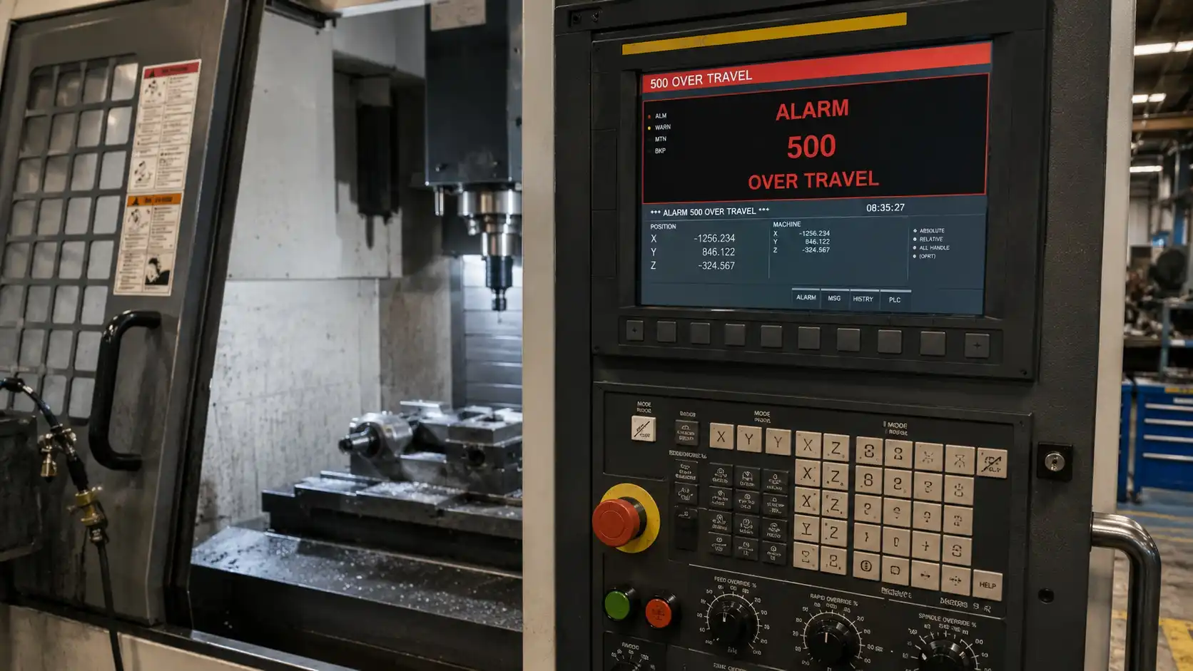
FANUC Alarm 500 Over Travel Error occurs when an axis moves beyond its permitted travel limit. The cause may be a triggered limit switch, incorrect machine position, lost reference return, faulty encoder feedback, or incorrect stroke limit parameters. In many cases, the alarm can be cleared by moving the axis away from the limit and performing a proper reference return.
What Is FANUC Alarm 500 Over Travel Error?
Alarm 500 is one of the most common FANUC alarms encountered in CNC machining centers and lathes.
The control generates this alarm whenever an axis exceeds its allowable travel range.
The purpose of the alarm is simple:
Prevent the machine from damaging itself.
Without overtravel protection, a machine could crash into physical stops, damage ball screws, bend way covers, destroy limit switches, or even damage expensive spindle assemblies.
For that reason, Alarm 500 should never be ignored or bypassed without understanding the root cause.
Does Alarm 500 Mean the Same Thing on Every FANUC Control?
Not always.
Although Alarm 500 is commonly associated with an overtravel condition on many FANUC-controlled machines, alarm numbering and alarm descriptions can vary depending on the FANUC generation, control series, and machine builder.
FANUC provides the CNC platform, but machine manufacturers often customize alarm screens, diagnostic pages, parameter structures, and operator messages. As a result, two machines may display different alarm text even when the underlying issue is essentially the same.
For example, some controls may simply display “500 OVER TRAVEL,” while others identify the affected axis or specify whether the machine has encountered a soft overtravel, hard overtravel, or stored stroke limit violation.
This is one reason experienced technicians rarely diagnose a machine based solely on the alarm number.
Instead, they verify:
- The complete alarm description
- The affected axis
- Machine coordinates
- Reference return status
- Active diagnostic signals
Operators should always read the exact alarm message shown on the control screen and consult the machine documentation when necessary.
The troubleshooting methods in this guide apply broadly to FANUC overtravel conditions regardless of minor alarm-number differences. Whether the control reports a hard overtravel, soft overtravel, stored stroke limit alarm, or axis travel limit violation, the same diagnostic principles generally apply.
Which FANUC Parameters Control Over Travel Limits?
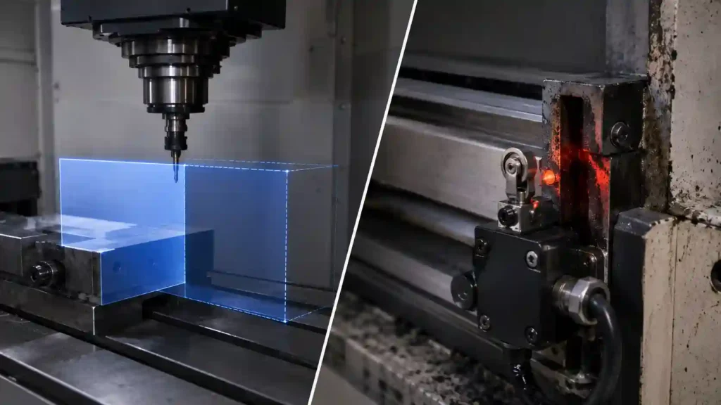
Every FANUC-controlled machine operates within predefined axis travel limits known as stored stroke limits.
These limits tell the CNC where each axis is allowed to travel relative to machine zero and reference position. If the control calculates that an axis has moved beyond those limits, it generates an overtravel alarm to prevent mechanical damage.
The exact parameters used to define stored stroke limits vary significantly between FANUC generations and machine tool builders. Older controls, newer i-Series controls, and OEM-customized implementations may all use different parameter layouts.
For that reason, it is generally more useful to understand the concept of stored stroke limits than to focus on specific parameter numbers that may not apply to every machine.
One situation service technicians encounter surprisingly often occurs after battery replacement, parameter restoration, control upgrades, or maintenance work involving backups. A machine may suddenly begin generating Alarm 500 even though no mechanical issue exists.
In many of these cases, incorrect parameter data has been restored into the control. The machine’s physical position is normal, but the stored stroke limit values no longer match the actual machine travel range.
The result is a false overtravel condition.
Before changing any travel-limit-related parameter:
- Verify machine coordinates
- Confirm reference return status
- Check whether recent parameter restoration occurred
- Compare current data with known-good backups
- Consult machine documentation
When stored stroke limits are configured correctly, Alarm 500 serves as an important protection system. When they are configured incorrectly, the control may report an overtravel condition even when the axis is physically well within its allowable travel range.
Why Does FANUC Alarm 500 Occur?
Several different situations can trigger this alarm.
1. The Axis Reached a Physical Limit
This is the most obvious scenario.
The machine physically travels too far until a limit switch is activated.
Common examples include:
- Incorrect work offsets
- Manual jogging errors
- Wrong MDI commands
- Programming mistakes
Programming mistakes are also a common cause of unexpected machine movement. Many Alarm 500 incidents can be traced back to positioning, offset, or motion-command errors similar to those discussed in our CNC Programming Errors guide.
In many shops this happens after setup changes when operators manually jog close to machine limits.
2. Lost Reference Position
After battery failure, encoder issues, or maintenance work, the CNC may lose its understanding of where the axis actually is.
The control may believe the machine is outside its allowed travel range even when it physically appears normal.
A lost reference position is one of the most common causes of recurring overtravel alarms.
Understanding how CNC controls track machine position is critical when diagnosing these faults. If you are unfamiliar with machine coordinates, work offsets, and reference positions, our CNC Basics guide provides a useful foundation.
3. Incorrect Stroke Limit Parameters
FANUC uses stroke limit parameters to define allowable travel.
If someone modifies these parameters incorrectly:
- X axis limits may become too small
- Y axis travel may be restricted
- Z axis may generate immediate OT alarms
This often appears after parameter restoration or machine rebuilding.
4. Faulty Limit Switches
Mechanical limit switches eventually wear.

A failed switch may remain activated even when the axis is nowhere near the machine limit.
Typical symptoms include:
- Alarm appears immediately after startup
- Axis cannot move in either direction
- Alarm returns instantly after reset
5. Encoder Position Errors
Absolute encoder systems continuously track machine position.
If encoder feedback becomes corrupted, the CNC may calculate an impossible axis position.
Although less common, encoder-related OT alarms usually require deeper troubleshooting.
Soft Over Travel vs Hard Over Travel
Understanding this distinction saves significant troubleshooting time.
| Type | Description | Severity |
|---|---|---|
| Soft Over Travel | Software limit exceeded | Usually easy to recover |
| Hard Over Travel | Physical limit switch activated | Requires manual recovery |
| Reference Position Error | Position calculation issue | Moderate |
| Parameter Error | Incorrect travel settings | Moderate to severe |
A surprising number of operators assume every OT alarm is mechanical.
In reality, many are software-related.
Can Over Travel Damage a CNC Machine?
Yes.
The severity depends on whether the machine stopped because of a soft overtravel condition or because it physically reached a hard overtravel limit.
In a soft overtravel situation, the control usually detects the problem before any mechanical contact occurs. These cases rarely cause damage and are often resolved through proper recovery procedures.
Hard overtravel situations are different.
If an axis continues moving until it reaches a physical stop, substantial mechanical loads can develop throughout the machine structure. Depending on machine design and travel speed, the following components may be affected:
- Ball screws
- Limit switches
- Axis couplings
- Way covers
- Servo motors
- Bearing assemblies
In severe cases, a mechanical crash can occur.
One practical observation from service work is that repeated contact with travel limits is often more damaging than a single incident. Operators occasionally develop the habit of forcing an axis against a limit while attempting to clear an alarm or locate machine zero. Even when no immediate damage is visible, repeated impacts can loosen switch brackets, damage couplings, distort way cover components, and increase long-term wear.
Another misconception is that servo systems will always protect the machine.
Servo overload protection helps reduce damage, but it cannot eliminate mechanical stress once the machine reaches a physical stop.
For that reason, Alarm 500 should be treated as a warning to investigate the cause rather than something that should simply be reset and ignored.
How to Reset FANUC Alarm 500
Method 1: Move the Axis Away from the Limit
If the machine is sitting on a hard limit switch:
- Press Emergency Stop.
- Enter manual mode.
- Hold the OT Release button if equipped.
- Carefully jog the affected axis away from the limit.
- Reset the alarm.
Machine manufacturers implement this differently, so procedures may vary.
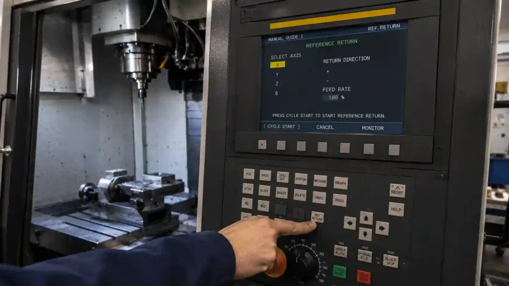
Method 2: Perform Reference Return
Once the axis is safely away from the limit:
- Enter Reference Return mode.
- Home the affected axis.
- Home all remaining axes.
- Verify machine coordinates.
Many recurring OT alarms disappear after a successful reference return.
Method 3: Verify Machine Coordinates
Check the machine coordinate screen.
If the position looks unreasonable, such as:
- X = 99999
- Y = -99999
the control may have lost position information.
In that situation, reference return or encoder diagnosis becomes necessary.
Diagnosing Which Axis Caused the Alarm
Most controls identify the affected axis directly.
Examples:
- X Over Travel
- Y Over Travel
- Z Over Travel
If not displayed clearly:
Check:
- Alarm details page
- Diagnostic screen
- Servo status screen
Knowing which axis triggered the fault dramatically narrows troubleshooting.
How Service Technicians Approach Over Travel Alarms
Experienced CNC service technicians rarely begin troubleshooting by replacing parts.
The first objective is determining whether the machine truly has a hardware problem or whether the control simply believes it is outside its allowable travel range.
The diagnostic process usually starts with machine coordinates.
If the machine coordinates appear unrealistic or inconsistent with the actual axis location, the technician immediately investigates reference return status, encoder position information, and machine zero settings.
If coordinates appear normal, attention shifts toward travel-limit systems.
This typically includes:
- Checking active limit switch signals
- Reviewing recent maintenance history
- Verifying stored stroke limits
- Confirming proper reference return
- Inspecting axis travel behavior
One pattern appears repeatedly in the field.
Operators often suspect servo failure because Alarm 500 prevents movement. However, many of these machines ultimately have no servo-related fault at all.
Instead, the root cause is often:
- A failed limit switch
- Lost reference position
- Incorrect machine coordinates
- Corrupted parameter data
- Improper recovery after battery replacement
This is why experienced technicians avoid jumping directly to servo diagnostics.
A machine that cannot move does not automatically have a servo problem.
The most efficient troubleshooting approach is to first verify where the control believes the machine is located. Once that information is confirmed, most overtravel alarms become significantly easier to diagnose.
In many cases, the actual repair takes only a few minutes. The challenge is identifying the correct cause before unnecessary adjustments or parts replacements create additional problems.
Common Real-World Causes
Incorrect Work Offset
A wrong G54 value can easily send a machine beyond travel limits.
This frequently happens when:
- New fixtures are installed
- Work offsets are copied
- Inch and metric values become mixed
Program Restart Mistakes
Many overtravel incidents occur after restarting a program mid-cycle.
Many restart-related problems originate from positioning commands that are not fully understood by the operator. Differences between absolute and incremental positioning can dramatically affect machine movement, as explained in Absolute vs Incremental CNC Positioning (G90 vs G91).
The machine may attempt to:
- Return to a previous coordinate
- Re-enter cutter compensation
- Retrace an unexpected toolpath
Unexpected rapid movements often occur when positioning commands are misunderstood. Reviewing the differences between G00 and G01 can help prevent some overtravel situations during setup and program verification.
What looked safe during simulation suddenly exceeds machine travel.
Tool Length Offset Errors
A large H offset can make the control calculate impossible positions.
The machine may generate an OT alarm before movement even begins.
This often surprises newer operators because the machine never actually moves.
How to Check the Limit Switch
If the alarm repeatedly returns:
Inspect:
- Switch mounting
- Damaged wiring
- Coolant contamination
- Broken actuator arms
One practical observation:
Limit switches rarely fail completely overnight.
More often they become intermittent first.
Operators may notice occasional alarms for weeks before complete failure occurs.
When the Alarm Appears After Battery Replacement
This scenario is extremely common.
If batteries are replaced with power off:
- Absolute position data may be lost.
- Reference position information disappears.
- OT alarms may appear immediately.
In many cases:
- Clear alarms.
- Perform reference return.
- Verify machine coordinates.
That restores normal operation.
Why the Alarm Keeps Coming Back
Resetting the alarm is easy.
Finding the root cause is harder.
If Alarm 500 returns repeatedly, investigate:
- Damaged limit switches
- Encoder feedback issues
- Loose servo connections
- Parameter corruption
- Mechanical overrun
- Improper machine zero settings
A machine that repeatedly enters overtravel mode usually has an underlying issue that has not been corrected.
Professional Troubleshooting Sequence
Experienced service technicians generally follow this order:
- Identify affected axis.
- Check machine coordinates.
- Verify reference return status.
- Inspect limit switch operation.
- Review recent parameter changes.
- Check encoder alarms.
- Test machine travel limits.
This approach avoids replacing expensive components unnecessarily.
One counterintuitive observation:
Many suspected servo failures ultimately turn out to be simple limit switch problems.
Alarm 500 on Machining Centers vs CNC Lathes
Although Alarm 500 always indicates an overtravel condition, the most common causes often vary depending on machine type.
Vertical Machining Centers
On vertical machining centers, Z-axis overtravel conditions are particularly common.
Typical causes include:
- Incorrect tool length offsets
- Improper work offset values
- Setup changes
- Manual jogging errors during setup
Many VMC overtravel incidents occur immediately after fixture changes or first-part prove-outs.
Horizontal Machining Centers
Horizontal machining centers introduce additional complexity because of pallet systems, rotary axes, and larger machine travels.
Common causes include:
- Incorrect work coordinate systems
- Rotary axis positioning errors
- Reference return issues
- Travel limit parameter mismatches
Because horizontal machines often have larger work envelopes, coordinate-related mistakes can remain unnoticed until rapid positioning commands occur.
CNC Lathes
On CNC lathes, X-axis and Z-axis travel issues are the most common sources of Alarm 500.
Frequently encountered causes include:
- Incorrect geometry offsets
- Wrong tool nose compensation values
- Turret recovery procedures
- Reference return problems after maintenance
In lathe applications, operators sometimes mistake offset-related travel problems for servo faults because the machine appears unable to move normally.
Regardless of machine type, the troubleshooting fundamentals remain largely the same:
- Verify machine coordinates
- Confirm reference return
- Inspect limit switches
- Review offsets
- Check stored stroke limits
A solid understanding of CNC machine positioning and coordinate systems makes troubleshooting significantly easier. Operators who regularly work with machine coordinates, work offsets, and reference return procedures typically diagnose Alarm 500 conditions much faster. For a broader overview, see What Is CNC Machining?.
The machine configuration changes, but the diagnostic logic usually remains consistent.
How to Prevent Future Over Travel Alarms
Several habits dramatically reduce OT incidents.
Verify Work Offsets
Always double-check:
- G54
- G55
- G56
- Tool offsets
before running a new setup.
Reference Return Daily
Many shops make homing part of the startup procedure.
This ensures coordinate consistency.
Avoid Excessive Manual Jogging
Large rapid jog movements near machine limits create unnecessary risk.
Inspect Limit Switches During Maintenance
Limit switches are inexpensive compared to downtime.
Checking them periodically prevents many production interruptions.
Real-World Example: An Over Travel Alarm That Wasn’t a Servo Failure

A few years ago, a vertical machining center repeatedly generated Alarm 500 every morning during startup.
The operators were convinced the problem was servo-related.
The alarm appeared intermittently, sometimes disappearing after a reset and sometimes preventing the machine from becoming operational. Because the issue seemed random, attention quickly shifted toward the servo amplifier and encoder system.
The first step was checking machine coordinates.
Surprisingly, all axis positions appeared normal. Reference return was completed successfully, machine zero was correct, and no servo alarms were present.
The machine could often run normally for several hours before the alarm returned.
That behavior suggested the problem was unlikely to be a failed servo drive.
Further inspection focused on the overtravel circuit itself.
After removing the protective cover near one axis limit switch, coolant contamination was discovered inside the switch housing. The switch was not permanently failed, but coolant residue occasionally prevented the internal contacts from fully releasing.
As a result, the control intermittently interpreted the switch as active and generated an overtravel condition.
After cleaning the area and replacing the switch, the problem disappeared completely.
Cases like this are a useful reminder that the most obvious diagnosis is not always the correct one. In the field, many suspected servo failures ultimately turn out to be relatively simple issues involving limit switches, wiring, reference return status, or machine coordinate data.
FANUC Alarm 500 FAQ
Can I simply disable the overtravel alarm?
No.
The alarm protects the machine from physical damage.
Disabling it creates significant crash risk.
Is Alarm 500 always a limit switch problem?
No.
Work offsets, encoder position loss, reference return issues, and parameter errors can also trigger it.
Why does Alarm 500 appear after power-up?
The machine may have lost reference position information or detected an active limit switch.
Can a battery cause Alarm 500?
Indirectly, yes.
Loss of absolute position data after battery failure can generate overtravel conditions.
Is it safe to keep resetting the alarm?
Only after identifying the cause.
Repeatedly resetting without diagnosis can lead to machine damage.
How Do I Clear FANUC Alarm 500?
In most cases, Alarm 500 can be cleared by moving the affected axis away from the overtravel condition and performing a proper reference return. If the alarm was caused by a soft overtravel condition, verifying machine coordinates and returning the machine to its home position is often sufficient. If the alarm returns immediately, further diagnosis of limit switches, stored stroke limits, or encoder position data may be necessary.
What Is the Difference Between Soft and Hard Overtravel?
A soft overtravel occurs when the CNC control calculates that an axis has exceeded its programmed travel limits. A hard overtravel occurs when the machine physically reaches a limit switch or mechanical stop. Soft overtravel conditions are usually software-related, while hard overtravel conditions involve physical machine travel limits.
Can Alarm 500 Damage a CNC Machine?
The alarm itself does not cause damage. However, the condition that triggered the alarm can potentially damage the machine if ignored. Hard overtravel situations can place excessive stress on ball screws, couplings, limit switches, servo systems, and machine structures. Repeatedly forcing an axis against a travel limit can eventually create mechanical problems.
Why Does FANUC Alarm 500 Keep Returning?
Recurring Alarm 500 faults typically indicate an underlying issue that has not been corrected. Common causes include faulty limit switches, incorrect stored stroke limits, lost reference return data, encoder position problems, parameter restoration errors, or machine coordinate inconsistencies. Simply resetting the alarm rarely solves the root cause.
Key Takeaways for Preventing Future Over Travel Alarms
FANUC Alarm 500 Over Travel Error is usually not a major failure. Most cases involve machine position errors, triggered limit switches, or lost reference data rather than expensive hardware damage.
Most Alarm 500 events are caused by coordinate, reference return, limit switch, or parameter issues rather than major hardware failures. A systematic troubleshooting process almost always identifies the root cause faster than replacing components based on assumptions.